{{schematic}} if possible.Sequential Chips[]
Latches and Flip-Flops are effectively 1-bit memory cells. They allow circuits to store data and deliver it at a later time, rather than acting only on the inputs at the time they are given. Functions using these components can be built to give different outputs in subsequent executions even if the inputs don't change, and so circuits using them are referred to as "sequential logic". They allow for the design of counters, long-term clocks, and complex memory systems, which cannot be created with combinational logic gates alone.
The common feature at the heart of every redstone latch or flip-flop is the RS NOR latch, built from two NOR gates whose inputs and outputs are connected in a loop (see below). The basic NOR latch's symmetry makes the choice of which state represents 'set' an arbitrary decision, at least until additional logic is attached to form more complex devices. Latches usually have two inputs, a 'set' input and a 'reset' input, used to control the value that is stored, while flip-flops tend to wrap additional logic around a latch to make it behave in different ways.
RS NOR latch[]

RS NOR latch designs.

RS NOR latch E design.

Example of design A RS NOR Latch. Here the latch is in the 'off' state.
A device where Q will stay on forever after input is received by S. Q can be turned off again by a signal received by R.
This is probably the smallest memory device that is possible to make in Minecraft. Note that Q means the opposite of Q, e.g. when Q is on, Q is off and vice-versa. This means that in certain cases, you can get rid of a NOT gate by simply picking the Q output instead of putting a NOT gate after the Q output.
A very basic example of use would be making an alarm system in which a warning light would stay turned on after a pressure plate is pressed, until you hit a reset button.
In the truth table, S=1, R=1 is often referred to as forbidden, because it breaks the inverse relationship between Q and Q. Also, some designs where the input is not isolated from the output, such as B and D, will actually result in Q and Q both apparently being 1 in this case. As soon as either S or R becomes 0, the output will be correct again. However, if S and R both become 0 on the exact same tick, the resulting state could be either Q or Q, depending on quirks of game mechanics. In practice, this input state should be avoided.
| S | R | Q | Q |
|---|---|---|---|
| 1 | 1 | 0 | 0 |
| 1 | 0 | 1 | 0 |
| 0 | 1 | 0 | 1 |
| 0 | 0 | Keep state | Keep state |
| Design | A | B | C | D | E | F | G |
|---|---|---|---|---|---|---|---|
| Size | 3x3x1 | 2x3x2 | 3x3x3 | 4x2x2 | 7x3x3 | 4x2x1 | 3x2x2 |
| Torches | 2 | 2 | 2 | 2 | 3 | 2 | 2 |
| Redstone | 4 | 4 | 8 | 6 | 18 | 4 | 3 |
| Inputs isolated? | Yes | No | Yes | No | Yes | Yes | Yes |
| Outputs isolated? | Yes | Yes | No | No | Yes | Yes | Yes |
| Input orientation | opposite | opposite | adjacent | either | adjacent | opposite | adjacent |
RS NAND latch[]
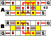
RS NAND latch designs.
Since NOR is the basic logic gate in Minecraft, a design for an RS NAND latch is just an RS NOR with inverters applied to the inputs and outputs.
When S and R are both off, Q and Q are on. When S is on, but R is off, Q will be on. When R is on, but S is off, Q will be on. When S and R are both on, it does not change Q and Q. They will be the same as they were before S and R were both turned on.
| S | R | Q | Q |
|---|---|---|---|
| 1 | 1 | Keep state | Keep state |
| 1 | 0 | 0 | 1 |
| 0 | 1 | 1 | 0 |
| 0 | 0 | 1 | 1 |
| Design | A | B |
|---|---|---|
| Size | 6x3x3 | 6x3x2 |
| Torches | 6 | 6 |
| Redstone | 10 | 8 |
| Input orientation | adjacent | opposite |
D Flip-Flop[]
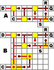
D flip-flop designs.

Side view of an upright D flip-flop, design C.
A D flip-flop, or "data" flip-flop, sets the output to D only on certain conditions. The basic level-triggering D flip-flop (design A), also known as a gated D latch, sets the output to D as long as the clock is set to OFF, and ignores changes in D as long as the clock is ON. Design B includes an edge-trigger, and will set the output to D only at the moment the clock goes from OFF to ON.
In these designs, the output is not isolated; this allows for asynchronous R and S inputs (which override the clock and force a certain output state). To get an isolated output, instead of using Q simply connect an inverter to Q.
Design C is a one block wide version of A, except for using a non-inverted clock. It sets the output to D as long as the clock is ON (turning the torch off). This design can be repeated in parallel every other block, giving it a much smaller footprint, equal to the minimum spacing of parallel data lines (when not using a "cable"). A clock signal can be distributed to all of them with a wire running perpendicularly under the data lines, allowing multiple flip-flops to share a single edge-trigger if desired. The output Q is most easily accessed in the reverse direction, toward the source of input. Q can be inverted or repeated to isolate the latch's Set line (the unisolated Q and Q wires can do double duty as R and S inputs, as in design A).
| Design | A | B | C |
|---|---|---|---|
| Size | 7x3x2 | 7x7x2 | 1x6x6 |
| Torches | 4 | 8 | 5 |
| Redstone | 11 | 18 | 8 |
| Trigger | Level | Edge | Level |
| Output isolated? | No | No | No |
| Input isolated? | Yes | Yes | C Only |
JK Flip-Flop[]
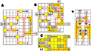
JK flip-flop designs.
An unclocked JK Flip-Flop works a lot like a RS NOR Latch. When the input J is ON and the input K is OFF, the output Q is ON. It will then hold that state until only K or both is ON. When only K is ON the Q is OFF. When both inputs are on they will start a race condition. This means that the output will keep changing until one of the inputs is turned OFF (It doesn't race fast enough to burn out the torches).
NOTE: Some of the illustrated JK Flip-Flops to the right don't include the typical inverse Q output. If you want to use the inverse Q then just add an inverter to the Q.
| Design | A | B | C |
|---|---|---|---|
| Size | 11x9x2 | 9x8x2 | 5x7x4 |
| Torches | 12 | 12 | 11 |
| Redstone | 34 | 35 | 22 |
| Accessible Q? | No | No | Yes |
| Trigger | Edge | Edge | Level |
T Flip-Flop[]
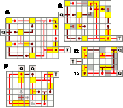
T flip-flop designs.
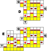
Side view of vertical T flip-flop designs.
T Flip-Flops are also known as "toggles". Whenever T changes from 0 (off) to 1 (on), the output will toggle its state.
A useful way to use T Flip-Flops in Minecraft could for example be a button connected to the input. When you press the button the output toggles (a door opens or closes), and does not toggle back when the button pops out. (Designs C and D do not have an incorporated edge trigger and will toggle multiple times unless the input is passed through one first.)
It is also the core of all binary counters and clocks, as it functions as a "period doubler", turning two input pulses into one output pulse.
Design A has a large footprint, but is easy to build. It (and B, which is a slightly compacted version of A) is essentially a JK flip-flop with the inputs for J and K removed so that it relies on the edge trigger (right side of the diagram) to keep it in the stable state and only allow a single operation per input.
Design C has a smaller footprint and an easily accessible inverse output, but lacks an edge trigger. If the input is kept high, it will repeatedly toggle on and off, cycling quickly enough to burn out its torches. For example, if the button mentioned above is wired directly to its input, the device can toggle several times before the button shuts off. Even a 4-clock is too slow to reliably result in only one toggle.
Adding an edge trigger by routing input through a separate pulse generator (design B' seems to work best) will prevent this problem, as will any other means of sending it a short (2-3 tick) pulse of power.
Designs D and E are much taller than the others, but only a single block wide, making them good for situations where floorspace is limited. D is level-triggered like design C, which can save space when distributing one input pulse to multiple flip-flops. E has a single block wide edge trigger added on, making it easy to daisy-chain multiple units to create a binary counter or period-doublers for a slow clock. These designs are based on the vertical gated D latch (design C) with the inverse output looped back to the input.
NOTE: Some of the illustrated T Flip-Flops to the right don't include the typical inverse Q outputs. If you want to use the inverse Q then just add an inverter to Q.
| Design | A | B | C | D | E |
|---|---|---|---|---|---|
| Size | 7x9x2 | 7x8x2 | 5x6x3 | 1x7x6 | 1x12x7 |
| Torches | 10 | 10 | 8 | 7 | 12 |
| Redstone | 28 | 29 | 22 | 9 | 15 |
| Accessible Q? | No | No | Yes | No | No |
| Trigger | Edge | Edge | Level | Level | Edge |
