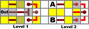
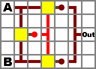
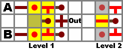
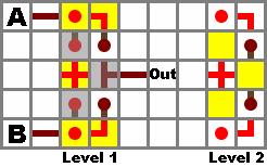
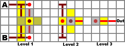
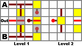
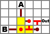
{{schematic}} if possible.Using redstone, one can implement logic gates in Minecraft. A Boolean logic gate performs a logical operation on one or more logic inputs and produces a single logic output. As in digital electronic circuits, simple redstone gates can be combined to form more complex redstone gates, which can be combined into even more elaborate devices.
Logic Gates[]
For each of the most common logic gates, possible redstone implementations are shown below. Note that most circuits have multiple valid implementations, each with various advantages and disadvantages. Important properties to consider are size (in each dimension), material requirements, location and isolation of the inputs and outputs, and speed, measured by the worst case number of ticks required by the gate to process the input.
By convention, a powered or lit torch or wire has a state of "1", while an unpowered torch or wire has a state of "0".
Not (Inverter)[]
Along with the Or gate, this is one of the simplest possible gates in Minecraft.
| Truth Table | Symbol | |
|---|---|---|
| In | Out | |
| 0 | 1 | |
| 1 | 0 | |
| Name (make this collapsible) | Properties | Diagram | Image | |
|---|---|---|---|---|
| A (or make each row collapsible) | Size: 1x1x2 Torches: 1 Redstone: 0 Input isolated: Yes Output Isolated: Yes |
diagram with logic gate symbols | ||
| Optional comments or quirks in the design | ||||
| B | Size: 1x1x2 Torches: 1 Redstone: 0 Input isolated: Yes Output Isolated: Yes |
diagram with logic gate symbols | image | |
Or[]
| Truth Table | Symbol | ||
|---|---|---|---|
| A | B | Out | |
| 0 | 0 | 0 | |
| 0 | 1 | 1 | |
| 1 | 0 | 1 | |
| 1 | 1 | 1 | |
A simpler version of the Or gate is design A: merely a wire connecting all inputs and outputs. However, this causes the inputs to become "compromised", so that they can only be used in this OR gate. If you need to use the inputs elsewhere, version B is necessary.
Note that design B is a simple inversion of a Nor gate.
Nor[]
Due to the simplicity and compactness of the Not and Or gates in Minecraft, the smallest and most efficient gates use the Nor as their fundamental building blocks. Any gate can be built entirely out of Nor gates.
This is the basic logic gate. A torch can have as many as 4 mutually isolated inputs (design B), but 3 can fit comfortably (design A), and all are optional. A torch with 1 input is the Not gate, and with no inputs is the True gate (i.e. a power source). If more inputs than 4 are necessary, one must resort to the non-isolated Or gate with a Not at the end (at expense of isolation), or multiple Nor gates, according to the formula A ⊽ B ⊽ C = A ⊽ ¬(B ⊽ C) (at the expense of speed, due to the nested gates).
| Truth Table | Symbol | ||
|---|---|---|---|
| A | B | Out | |
| 0 | 0 | 1 | |
| 0 | 1 | 0 | |
| 1 | 0 | 0 | |
| 1 | 1 | 0 | |
| Name | Properties | Diagram | Image | |
|---|---|---|---|---|
| A | Size: 1x1x2 Torches: 1 Redstone: 0 Input isolated: Yes Output Isolated: |
diagram with logic gate symbols |  Example of design A Nor gate. Input A is 1. | |
Nand[]
The simplest possible Nand gate must be constructed from two Not gates and an Or gate. This means that while it is possible to construct any gate using only Nand gates, the most efficient designs will revolve around the Nor gate.
| Truth Table | Symbol | ||
|---|---|---|---|
| A | B | Out | |
| 0 | 0 | 1 | |
| 0 | 1 | 1 | |
| 1 | 0 | 1 | |
| 1 | 1 | 0 | |
| Name | Properties | Diagram | Image | |
|---|---|---|---|---|
| A | Size: 3x1x2 Torches: 2 Redstone: 1 Input isolated: Output Isolated: |
diagram with logic gate symbols | image | |
| Optional comments or quirks in the design | ||||
| B | Size: 2x2x1 Torches: 2 Redstone: 1 Input isolated: Output Isolated: |
diagram with logic gate symbols | image | |
And[]
An AND gate returns true only when both its imputs are true
| Truth Table | Symbol | ||
|---|---|---|---|
| A | B | Out | |
| 0 | 0 | 0 | |
| 0 | 1 | 0 | |
| 1 | 0 | 0 | |
| 1 | 1 | 1 | |
Xor[]
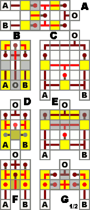
Xor gate designs.
| Truth Table | Symbol | ||
|---|---|---|---|
| A | B | Out | |
| 0 | 0 | 0 | |
| 0 | 1 | 1 | |
| 1 | 0 | 1 | |
| 1 | 1 | 0 | |
| Design | A | B | C | D | E | F | G |
|---|---|---|---|---|---|---|---|
| Size | 3x5x2 | 3x3x3 | 5x5x1 | 3x3x2 | 5x4x2 | 3x3x3 | 5x2x2 |
| Torches | 5 | 5 | 3 | 3 | 3 | 5 | 8 |
| Redstone | 6 | 5 | 14 | 3 | 12 | 4 | 4 |
| Speed (ticks) | 3 | 3 | 2 | 2 | 2 | 3 | 3 |
| Output direction | fwd. | rev. | fwd. | fwd. | fwd. | fwd. | fwd. |
| Requires levers? | No | No | No | Yes | No | No | No |
Xnor[]

Xnor gate designs.
| Truth Table | Symbol | ||
|---|---|---|---|
| A | B | Out | |
| 0 | 0 | 1 | |
| 0 | 1 | 0 | |
| 1 | 0 | 0 | |
| 1 | 1 | 1 | |
| Design | A | B | C | D | E | F |
|---|---|---|---|---|---|---|
| Size | 4x3x2 | 4x3x2 | 2x5x4 | 3x5x3 | 4x5x2 | 4x5x2 |
| Torches | 6 | 4 | 4 | 4 | 4 | 4 |
| Redstone | 5 | 5 | 7 | 7 | 10 | 9 |
| Speed (ticks) | 3 | 2 | 2 | 2 | 2 | 2 |
| Output direction | fwd. | fwd. | fwd. | fwd. | fwd. | rev. |
| Levers required? | No | Yes | No | No | No | No |
Implies[]
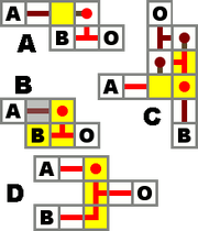
IMPLIES gate.
A device which represents material implication. Returns false only if the implication A → B is false, that is, if the conditional A is true, but the consequent B is false.
| Truth Table | Symbol | ||
|---|---|---|---|
| A | B | Out | |
| 0 | 0 | 1 | |
| 0 | 1 | 1 | |
| 1 | 0 | 0 | |
| 1 | 1 | 1 | |
| Design | A | B | C | D |
|---|---|---|---|---|
| Size | 2x2x1 | 2x1x2 | 2x3x2 | 1x3x2 |
| Torches | 1 | 1 | 3 | 1 |
| Redstone | 1 | 1 | 2 | 2 |
| Speed (ticks) | 1 | 1 | 2 | 1 |
| Inputs isolated? | Only A | Only A | Yes | Only A |
| Output isolated? | No | No | Yes | No |


